GPIOs as Inputs
Example 3.1
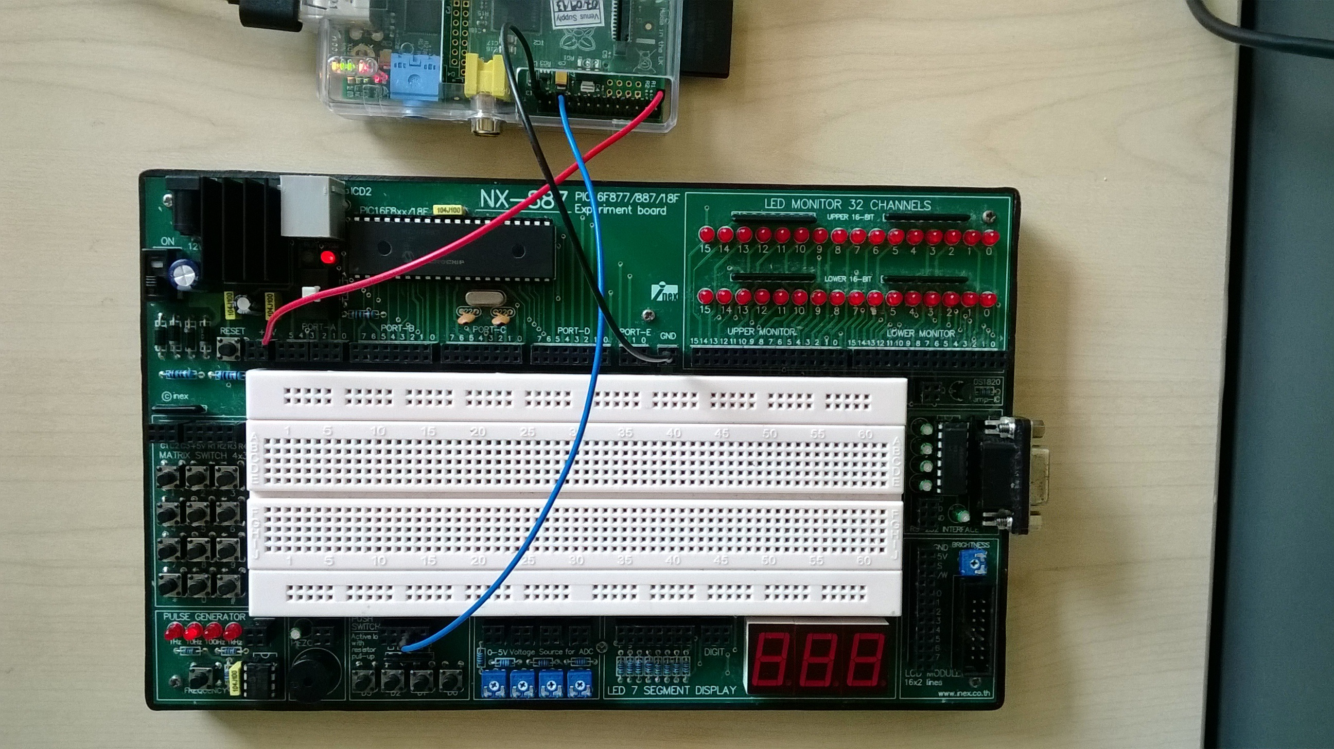
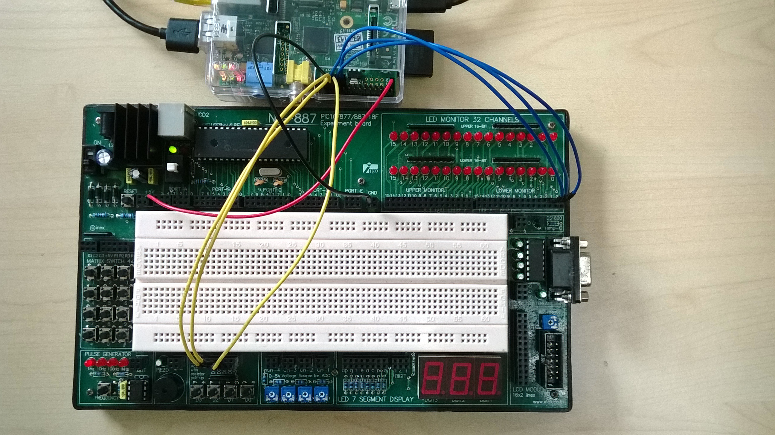
Make the following connections (see picture):
Ground and voltage supply:
- Connect PIN 25 (GROUND) to the GND of the experiment board.
- Connect PIN 1 (3.3V) of the Raspberry Pi to the +5V of the experiment board. Yes, you understood right, the 3.3V of the Pi to the +5V of the board, and NOT the 5V of the Pi to the 5V of the board!
Switch:
- Connect PIN 22 to switch 0 (socket D0 of the experiment board).
Then, run the following program (file example3.1):
import RPi.GPIO as GPIO # Import library for GPIO (pin) access
GPIO.setmode(GPIO.BOARD) # Specify that we use the BOARD numbers (pin numbers 1-26 on the connector)
GPIO.setwarnings(False) # Disable the warning “This channel is already in use”
import time
GPIO.setup(22, GPIO.IN) # Configure pin 22 as an input (IN)
while True:
x = GPIO.input(22) # Read pin 22 and store 1 (high) or 0 (low) in x
print(x) # print x. It will print either 1 or 0
time.sleep(0.25) # wait 0.25 seconds before doing the loop again
As you can see from the video, the GPIO.input function returns 1 (high) when the switch is NOT pressed and 0 (low) when the switch is pressed.
Example 3.2
Leave the same connections of the previous example and run the following program (file example3.2):
import RPi.GPIO as GPIO # Import library for GPIO (pin) access
GPIO.setmode(GPIO.BOARD) # Specify that we use the BOARD numbers (pin numbers 1-26 on the connector)
GPIO.setwarnings(False) # Disable the warning “This channel is already in use”
import time
GPIO.setup(22, GPIO.IN) # Configure pin 22 as an input (IN)
print(‘I am waiting that you press the button…’)
while True:
x = GPIO.input(22) # Read pin 22
if x == 0: # if the button is pressed…
break # … the break statements terminates the while loop
time.sleep(0.01) # wait 10ms before checking pin 22 again
print(‘Button pressed!’)
As shown in the video, the program “waits” inside the while loop until x becomes zero (button pressed). The break statement is used to exit from the while loop.
Assignment 3.A
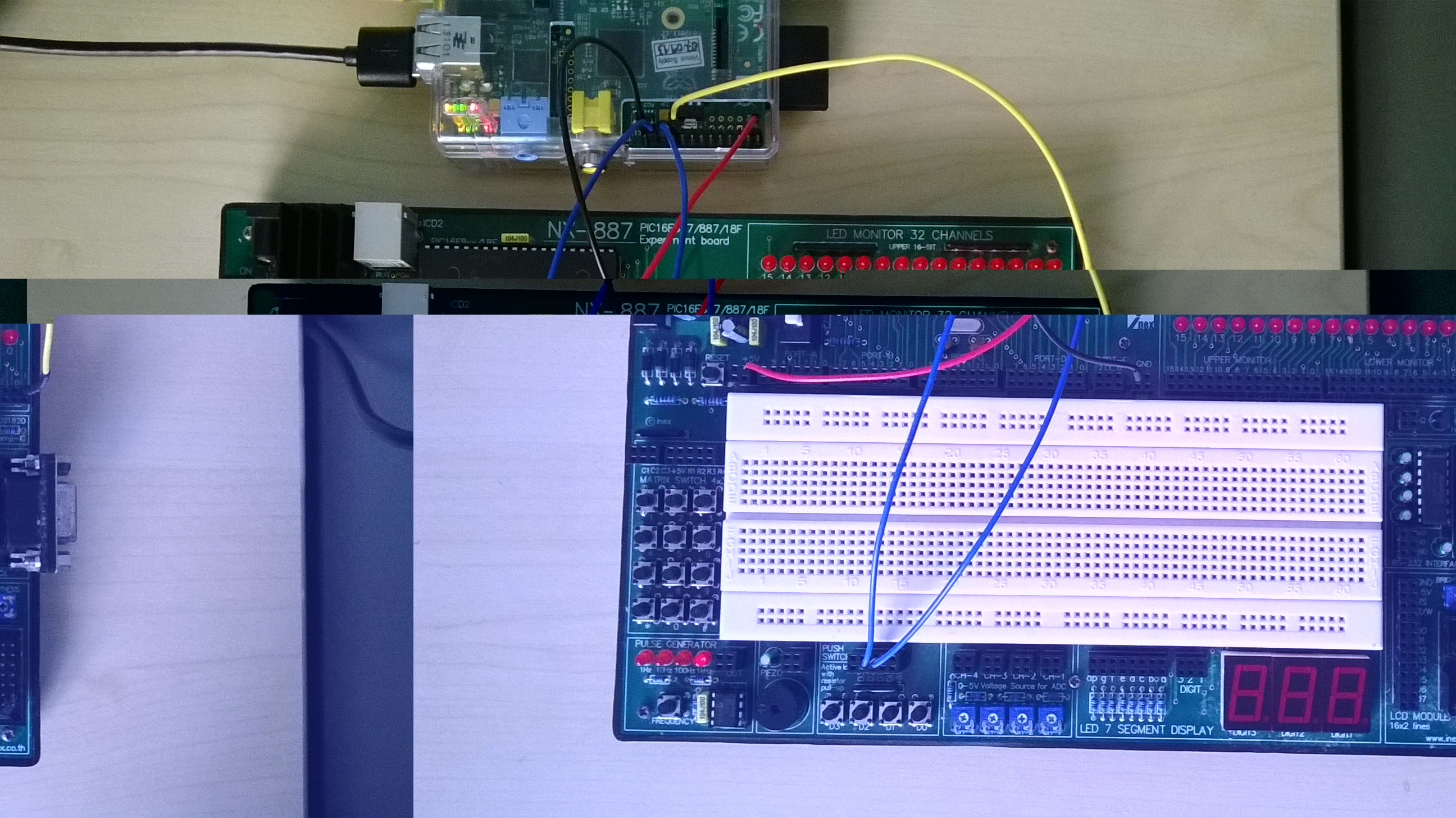
Add the following wire (picture):
- Connect PIN 19 to LED 0
Modify assignment 3.2. When the program starts, LED 0 should be off. When the user presses the switch, LED 0 turns on and the program terminates (see video).
Example 3.3
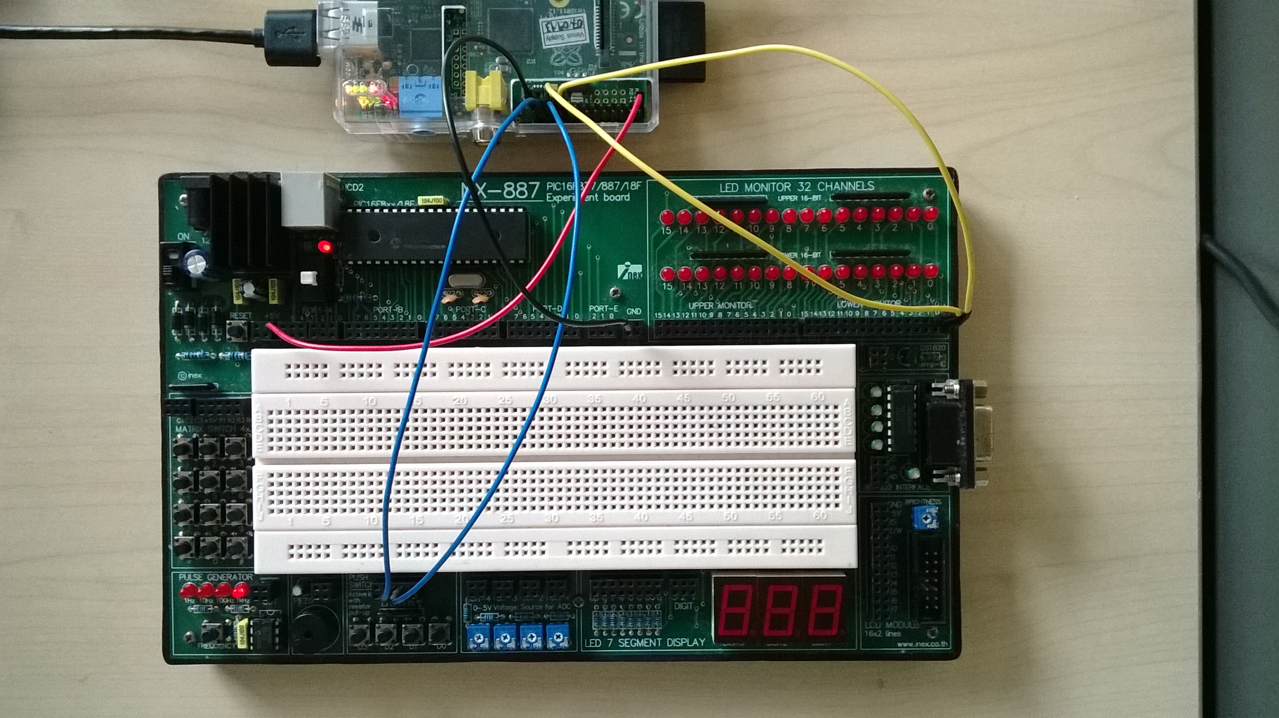
Add another wire (picture):
Connect PIN 24 to switch 1 (socket D1 on the experiment board)
Run the following program (file example3.3 and video):
import RPi.GPIO as GPIO # Import library for GPIO (pin) access
GPIO.setmode(GPIO.BOARD) # Specify that we use the BOARD numbers (pin numbers 1-26 on the connector)
GPIO.setwarnings(False) # Disable the warning “This channel is already in use”
import time
# **** PIN CONFIGURATIONS **********************************
GPIO.setup(22, GPIO.IN) # Configure pin 22 as input (IN)
GPIO.setup(24, GPIO.IN) # Configure pin 24 as input (IN)
GPIO.setup(19, GPIO.OUT) # Configure pin 19 as output (OUT)
# **********************************************************
GPIO.output(19, 0) # turn off the LED when the program starts
while True:
s0 = GPIO.input(22) # read switch 0
s1 = GPIO.input(24) # read switch 1
if s0 == 0: # if switch 0 is pressed…
GPIO.output(19, 0) # …turn off the LED
elif s1 == 0: # if switch 1 is pressed…
GPIO.output(19, 1) # …turn on the LED
time.sleep(0.01) # wait 10ms before checking the switches again
When the program starts the LED is off. Then:
- When the user presses switch 1, the LED turns on. The LED remains on after switch 1 is released.
- When the user presses switch 0, the LED turns off. The LED remains off after switch 0 is released.
Assignment 3.B
Add another wire (picture):
- Connect PIN 21 to LED 1.
The program should do as follows (see video):
- When the program starts both LEDs are off.
- When the user presses switch 0, LED 0 turns on LED 1 turns off. LED 0 should remain on after switch 0 is released.
- When the user presses switch 1, LED 1 turns on LED 0 turns off. LED 1 should remain on after switch 1 is released.
Assignment 3.C
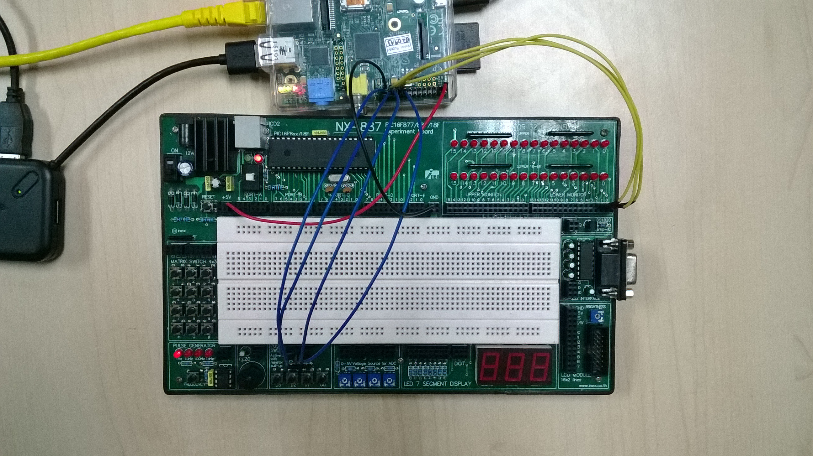
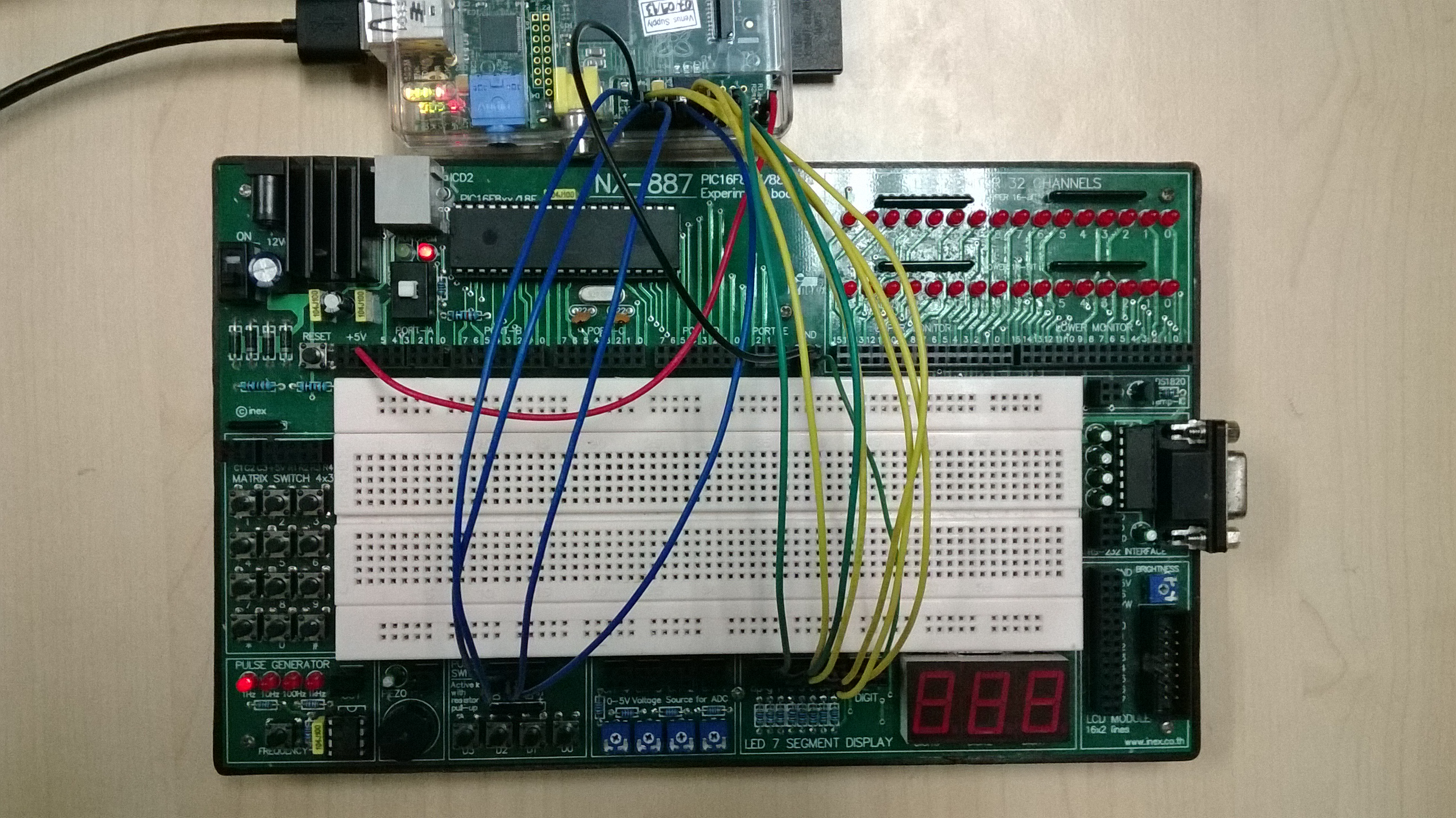
Ground and voltage supply (see picture):
- Connect PIN 25 (GROUND) to the GND of the experiment board.
- Connect PIN 1 (3.3V) of the Raspberry Pi to the +5V of the experiment board.
LEDs:
- Connect PIN 23 to LED 2.
- Connect PIN 21 to LED 1.
- Connect PIN 19 to LED 0.
Switches:
- Connect PIN 26 to switch 3 (D3).
- Connect PIN 24 to switch 2 (D2).
- Connect PIN 22 to switch 1 (D1).
- Connect PIN 18 to switch 0 (D0).
The program should work as follows (see video):
- When the program starts all the three LEDs are off.
- If the user presses switch 1, one LED (LED 0) should be on and all the other LEDs off.
- If the user presses switch 2, two LEDs should be on (LED 0 and LED 1) and LED 2 off.
- If the user presses switch 3, all three LEDs should be on.
- If the user presses switch 0, all three LEDs should be off.
Assignment 3.D
Modify the program of assignment 3.C. Use only switches 1, 2 and 3 (see picture). This time the LEDs are on as long as one of the switches 1,2,3 is pressed. When the switch is released the LEDs turn off. See the video. In other words:
- When the program starts all the three LEDs are off.
- If the user presses switch 1, one LED (LED 0) should be on and all the other LEDs off. When the user releases switch 1, LED0 turns off.
- If the user presses switch 2, two LEDs should be on (LED 0 and LED 1) and LED 2 off. When the user releases switch 2, LED0 and LED1 turn off.
- If the user presses switch 3, all three LEDs should be on. When the user releases switch 3, all the LEDs turn off.
Hint: use an if-elif-else statement in order to turn off all the LEDs when none of the switches if pressed.
Assignment 3.E
Ground and voltage supply (see picture):
- Connect PIN 25 (GROUND) to the GND of the experiment board.
- Connect PIN 1 (3.3V) of the Raspberry Pi to the +5V of the experiment board.
Switches:
- Connect PIN 26 to switch 3 (D3).
- Connect PIN 24 to switch 2 (D2).
- Connect PIN 22 to switch 1 (D1).
- Connect PIN 18 to switch 0 (D0).
Connect the 7-segment display as indicated in the section Seven Segment Display of Chapter 1.
The program should work as follows (see video):
- When the program starts the 7-segment display is off.
- If the user presses switch 0, the display shows 0. The display keeps displaying 0 after the user releases the switch.
- If the user presses switch 1, the display shows 1. The display keeps displaying 1 after the user releases the switch.
- If the user presses switch 2, the display shows 2. The display keeps displaying 2 after the user releases the switch.
- If the user presses switch 3, the display shows 3. The display keeps displaying 3 after the user releases the switch.
Assignment 3.F
Modify the program of assignment 3.E. This time the display should show the numbers 0,1,2,3 as long as the respective switch is pressed. When the switch is released the display should turn off. See the video. Hint: you should use an if-elif-else statement in order to turn off the display when none of the switches is pressed.
Assignment 3.G
Modify the program of assignment 3.F. This time, if the user presses more than one switch at the same time, the display should show E, for Error. Hint: use the and operator inside the if-elif-else to check the status of several switches at the same time. Look at the video.