Example 1.1
Make the following connections (see picture):
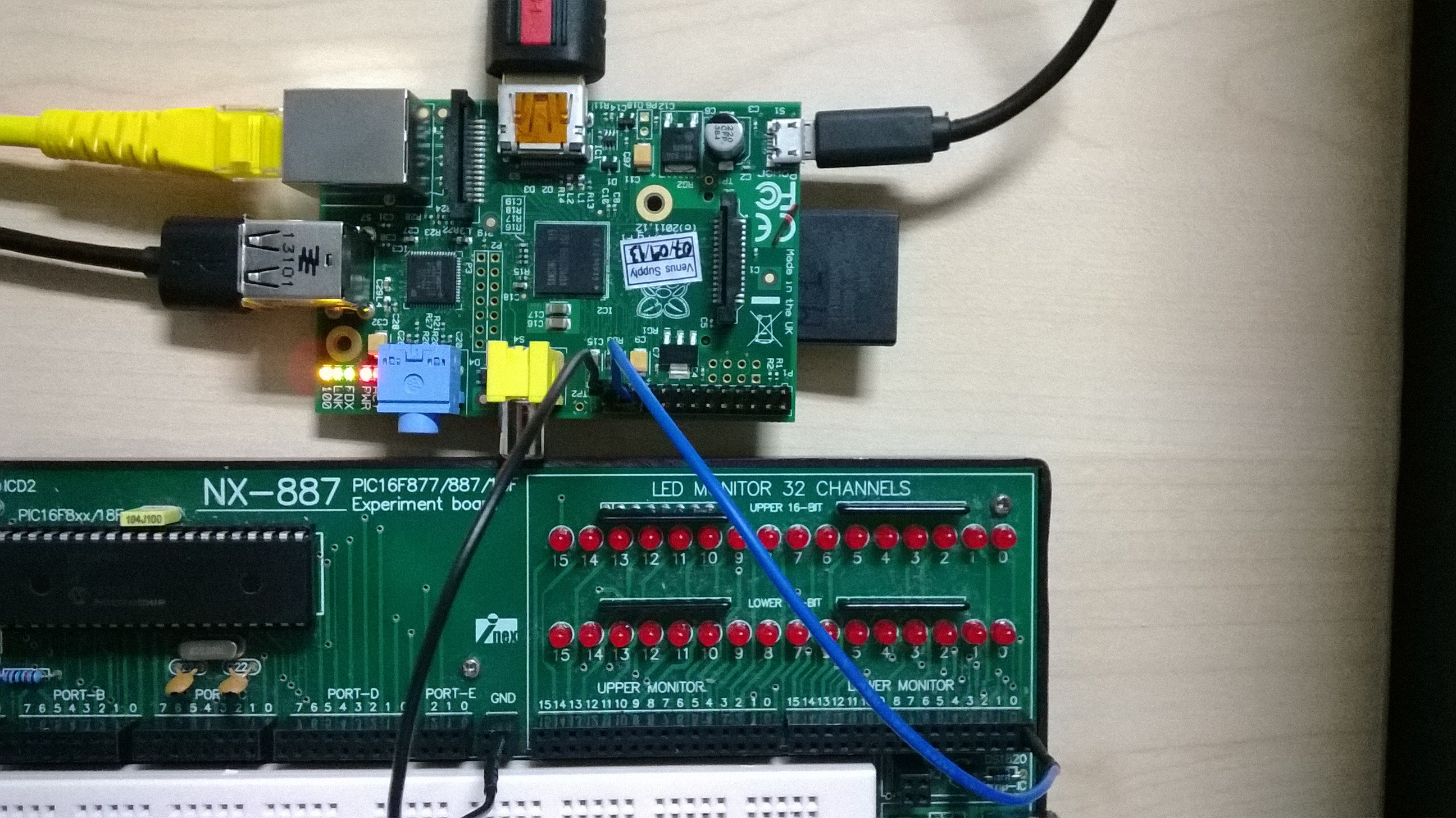

Connect PIN 25 (GROUND) of the Raspberry Pi to the GND of the experiment board.
Connect PIN 22 of the Raspberry Pi to LED 0 of the Lower Monitor on the experiment board.
Then, run the following program (file Example1_1):
import RPi.GPIO as GPIO # Import library for GPIO (pin) access
GPIO.setmode(GPIO.BOARD) # Specify that we use the BOARD numbers (pin numbers 1-40 on the connector)
GPIO.setwarnings(False) # Disable the warning “This channel is already in use”
# ******** PIN CONFIGURATION *************************************
GPIO.setup(22, GPIO.OUT) # Configure pin 22 as an output (OUT)
# ****************************************************************
GPIO.output(22, 1) # Send a logic 1 to pin 22, i.e. turn on the LED connected to pin 22
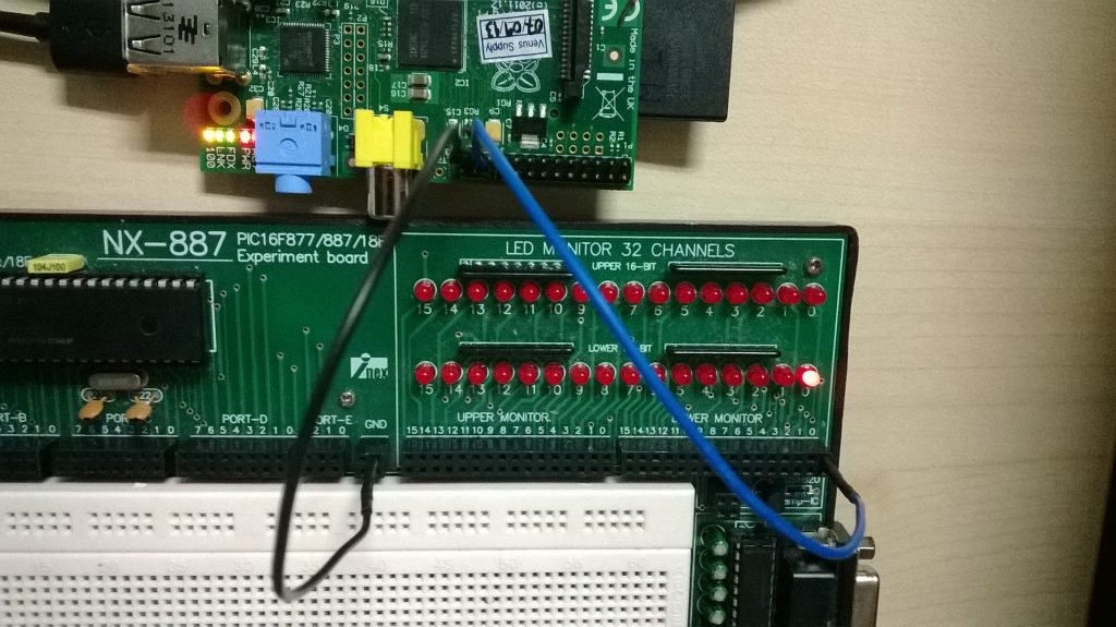
The program turns on LED 0 as you can see in this picture.
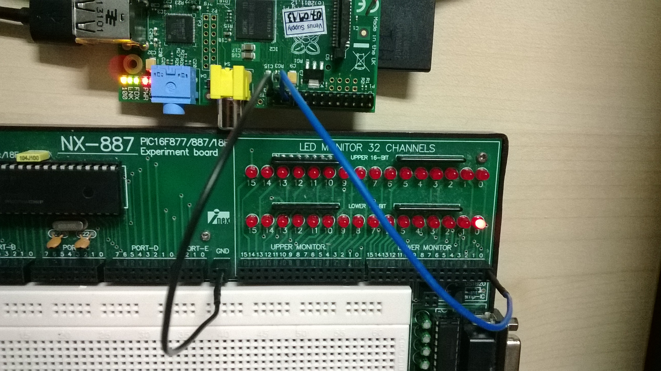
Assignment 1.A
After running Example 1.1, LED 0 is turned on. Now modify the program so that it turns off LED 0.