Example 1.1
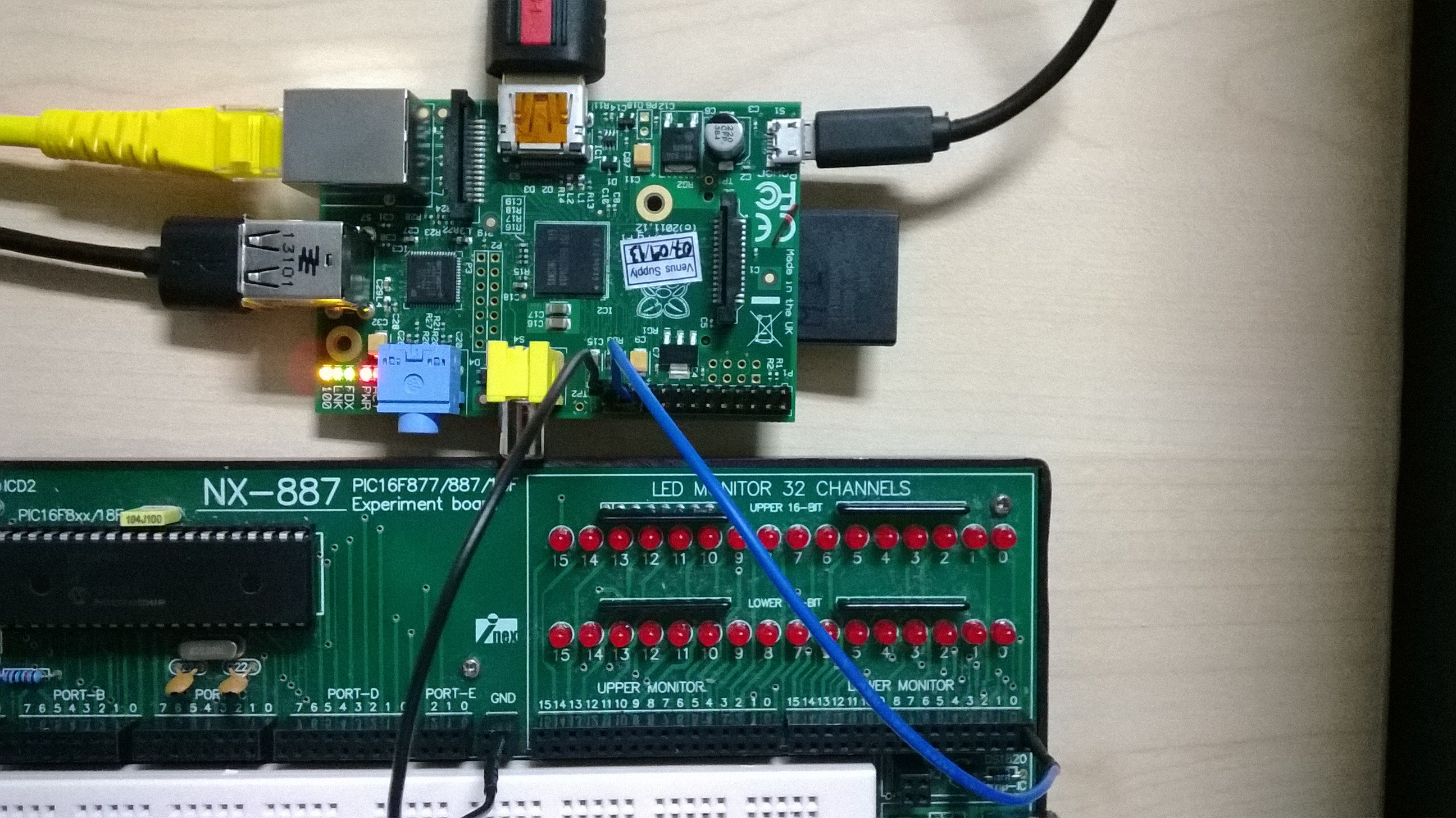
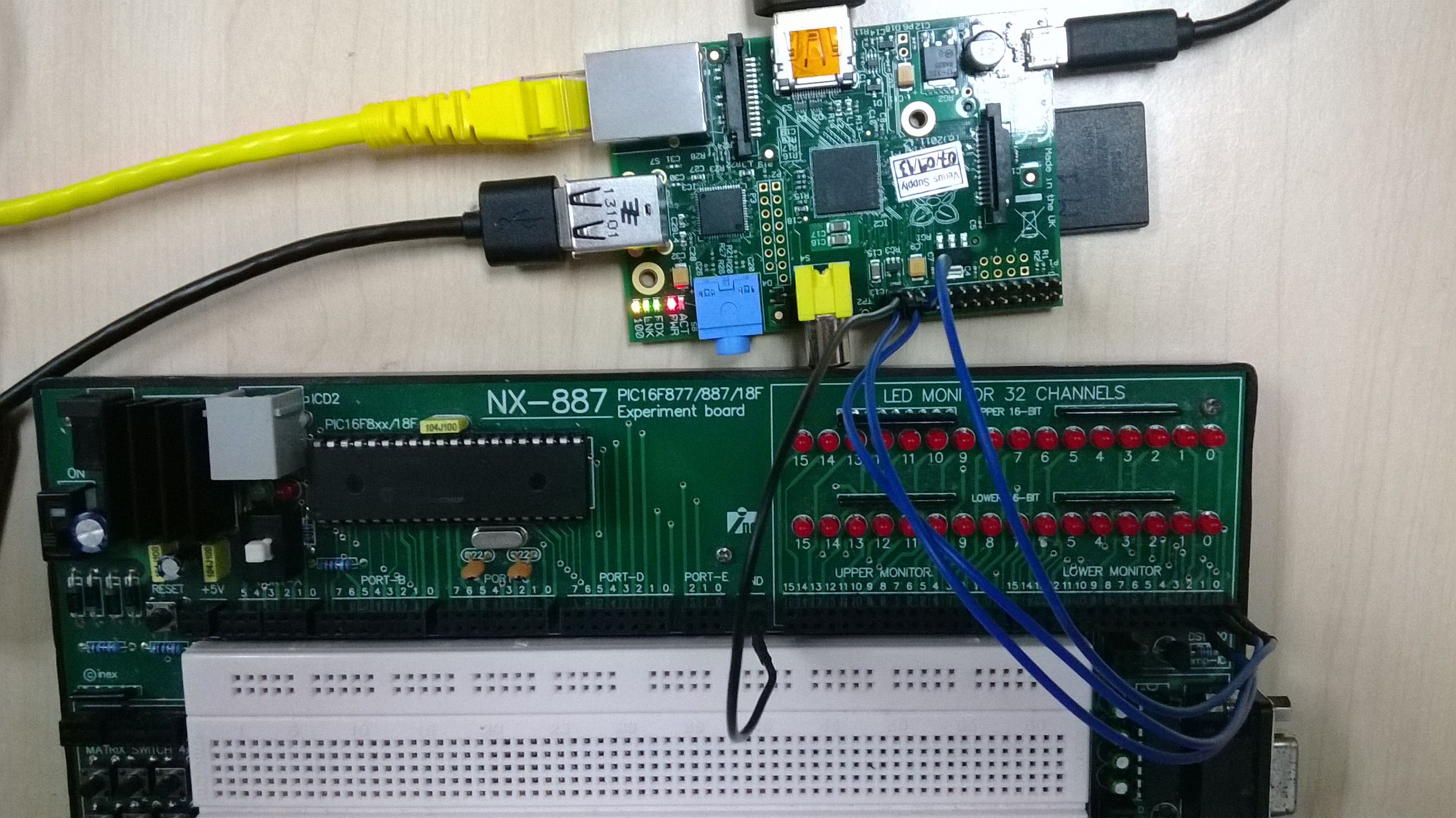
Make the following connections (see picture):
Connect PIN 25 (GROUND) of the Raspberry Pi to the GND of the experiment board.
Connect PIN 22 of the Raspberry Pi to LED 0 of the Lower Monitor on the experiment board.
Then, run the following program (file Example1_1):
import RPi.GPIO as GPIO # Import library for GPIO (pin) access
GPIO.setmode(GPIO.BOARD) # Specify that we use the BOARD numbers (pin numbers 1-40 on the connector)
GPIO.setwarnings(False) # Disable the warning “This channel is already in use”
# ******** PIN CONFIGURATION *************************************
GPIO.setup(22, GPIO.OUT) # Configure pin 22 as an output (OUT)
# ****************************************************************
GPIO.output(22, 1) # Send a logic 1 to pin 22, i.e. turn on the LED connected to pin 22
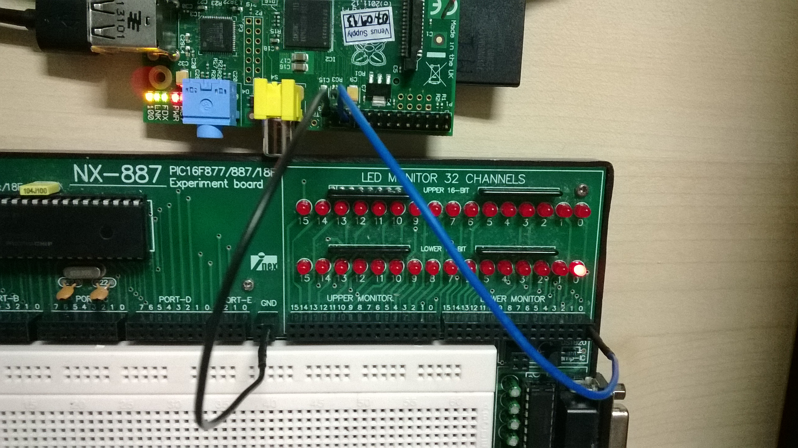
The program turns on LED 0 as you can see in this picture.
Assignment 1.A
After running Example 1.1, LED 0 is turned on. Now modify the program so that it turns off LED 0.
Assignment 1.B
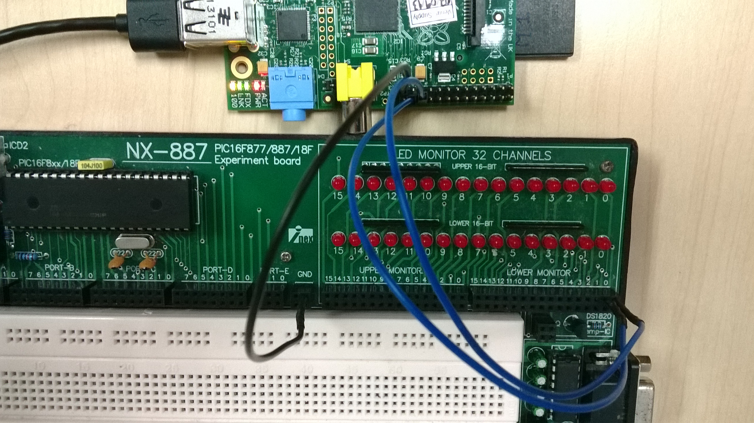
Add the following connection (see picture):
Connect PIN 24 of the Raspberry Pi to LED 1 of the Lower Monitor on the experiment board.
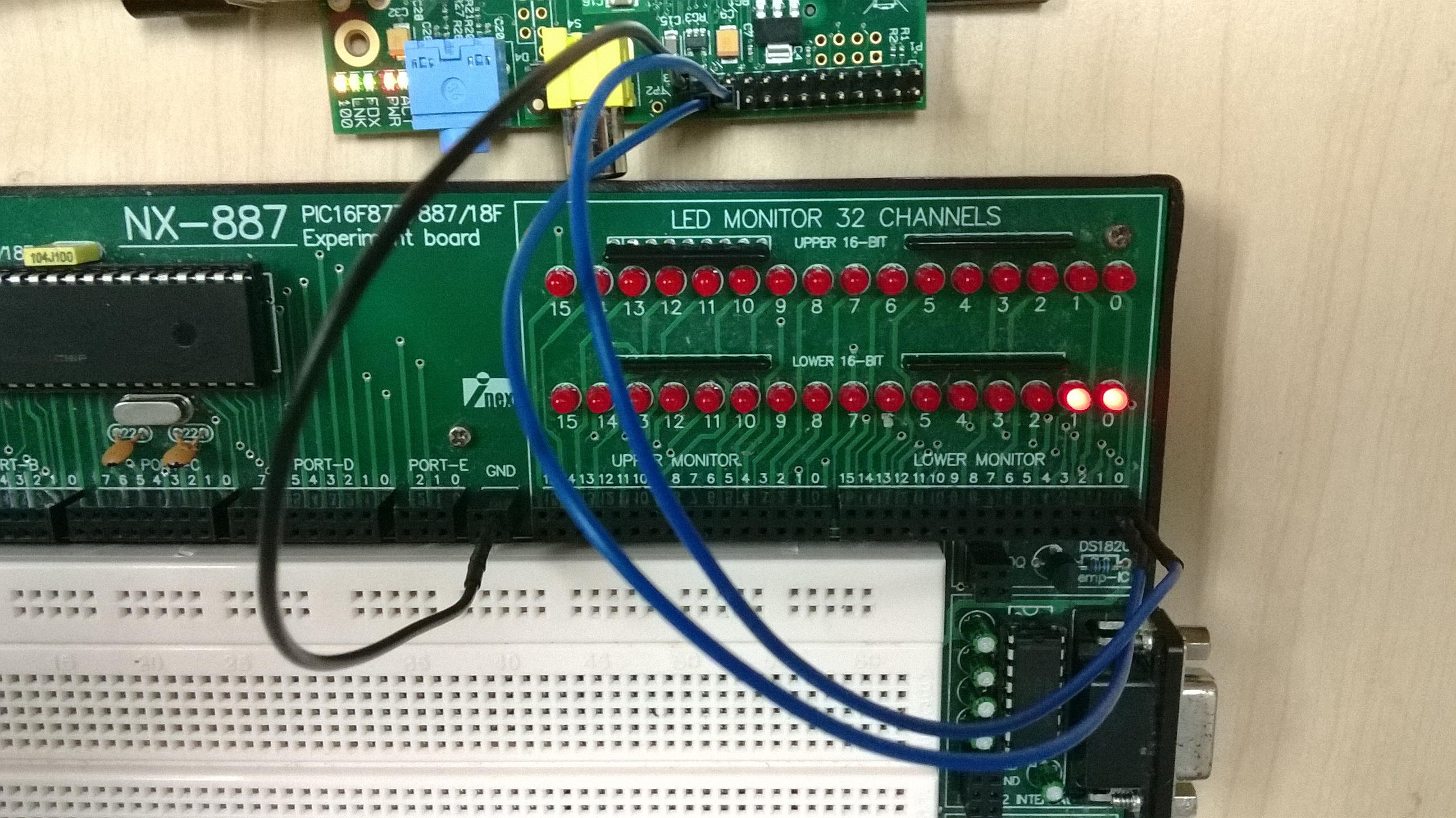
Modify the program of the previous assignment so that it turns on LED 0 and also LED 1 as in this picture.
Assignment 1.C
After running the program of assignment 1.B, LED 0 and LED1 are turned on. Modify the program so that it turns off LED 0 and LED 1.
Example 1.2
The following program (file Example1.2) is a modification of example 1.1. The program makes the LED blink for three times, using time intervals of 0.5 seconds (see video).
import time # Import the time library
import RPi.GPIO as GPIO # Import library for GPIO (pin) access
GPIO.setmode(GPIO.BOARD) # Specify that we use the BOARD numbers (pin numbers 1-40 on the connector)
GPIO.setwarnings(False) # Disable the warning “This channel is already in use”
# ******** PIN CONFIGURATION *************************************
GPIO.setup(22, GPIO.OUT) # Configure pin 22 as an output (OUT)
# ****************************************************************
GPIO.output(22, 1) # Send a logic 1 to pin 22, i.e. turn on the LED
time.sleep(0.5) # The program “waits” here for 0.5s
GPIO.output(22, 0) # Send a logic 0 to pin 22, i.e. turn off the LED
time.sleep(0.5) # The program “waits” here for 0.5s
GPIO.output(22, 1)
time.sleep(0.5)
GPIO.output(22, 0)
time.sleep(0.5)
GPIO.output(22, 1)
time.sleep(0.5)
GPIO.output(22, 0)
Assignment 1.D
Modify assignment 1.B. The two LEDs should blink three times as in this video. Use time intervals of 0.5 seconds.
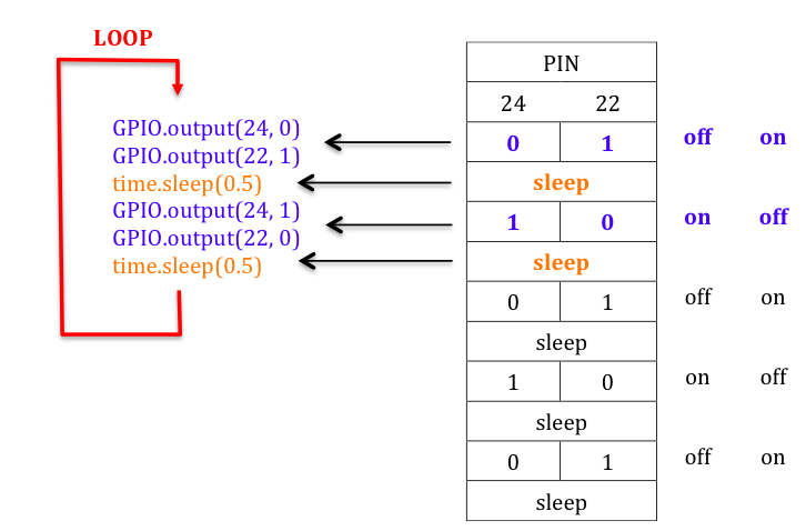
Assignment 1.E
Modify assignment 1.D. Now the two LEDs should blink three times but with a slightly different pattern as shown in this video. Use time intervals of 0.5 seconds.
Assignment 1.F
Add the following connection (see picture):
Connect PIN 26 of the Raspberry Pi to LED 2 of the Lower Monitor on the experiment board.
Write a program that “makes the light move” right-left-right as in this video.
Look at the section For and While Loops in Python and then continue with the next assignments.
Assignment 1.G
Modify example 1.2. Use an infinite loop to make LED 0 blink indefinitely (i.e. forever). Then, stop the program using CTRL+C.
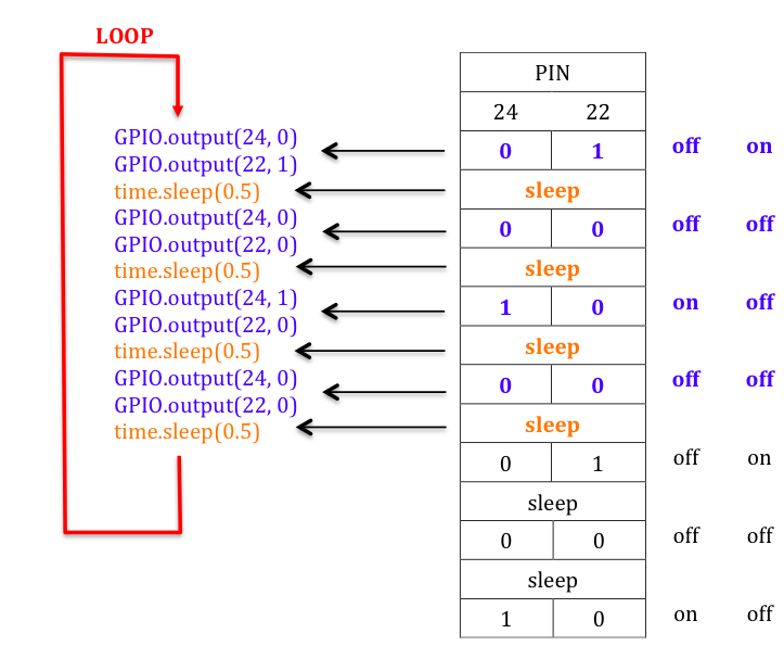
Assignment 1.H
Modify assignment 1.D. Use an infinite loop to make the two LEDs blink indefinitely. Hint:
Assignment 1.I
Modify assignment 1.E. Use an infinite loop to make the two LEDs blink indefinitely.
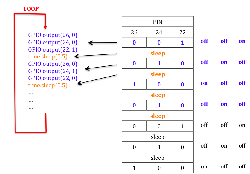
Assignment 1.J
Modify assignment 1.F. Use an infinite loop to make the light “move” right-left-right-left indefinitely. Hint:
Seven Segment Display
Connect PIN 25 (GROUND) of the Raspberry Pi to the GND of the experiment board. Then make the following connections between the Raspberry Pi pins and the 7-segment display socket (see picture):
Connect PIN 23 to a
Connect PIN 21 to b
Connect PIN 19 to c
Connect PIN 15 to d
Connect PIN 13 to e
Connect PIN 11 to f
Connect PIN 7 to g
You must also connect the common cathode of one of the three 7-segment displays (for instance DIGIT1) to GND.
The 7-segment display socket pins a, b, c,…,g, are connected to the 7 LEDs inside the display according to the following scheme:

Assignment 1.M
Write a program (see video) that displays the sequence 0, 1, 2 on the display and then turns off the display (i.e. all the LEDs should be off after the program terminates). Use time intervals of 1s.
Hints:
1. Configure the seven pins 23, 21, 19, 15, 13, 11, 7 as outputs.
2. Then, use a sequence of seven output functions for each of the rows in the table below to make the numbers 0, 1, 2 appear on the display. Obviously you have to complete the table first.

Assignment 1.N
Modify the previous assignment. This time the program should displays the sequence 0, 1, 2 indefinitely as shown in this video.